Modelling and Tuning
Modelling the controller
So this is the model of the MCU side:

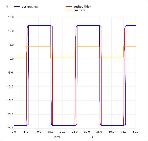
Then the high voltage push-pull:
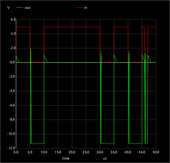
And finally the single-ended output:
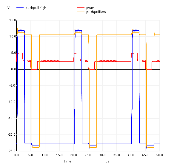
So this is currently modelling the major parts and this is very close to what is seem in the real circuit.
The experience with SPICE is much better than QUCS.
A person can spend hours just trying to coax a single simulation out of QUCS having to mess with the parameters to remove the Jacobian Singulars.
Even then it could take a while to run a simulation.
SPICE, on the other hand, seems to pretty instantly work so long as there are no silly errors.
And the output from a broken simulation is quite useful in fixing bugs in the circuit.
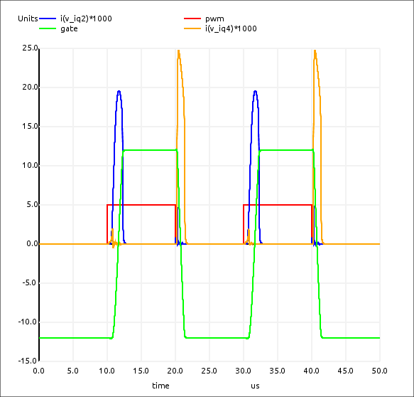
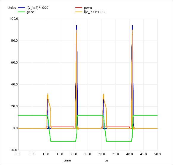
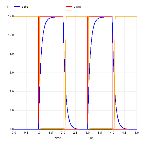
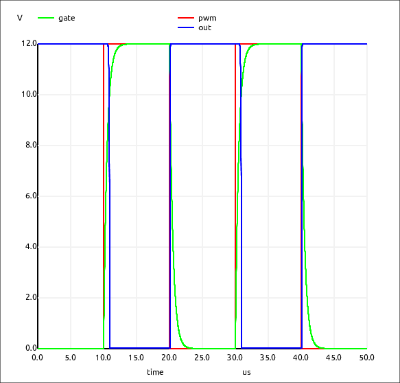
Refining the Push-Pull Design
Need to be able to charge/discharge the gate (which is just a capacitor in the model) in 1uS.
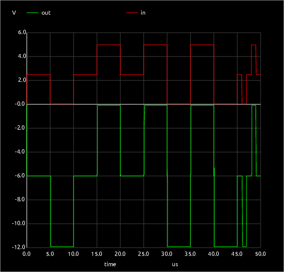
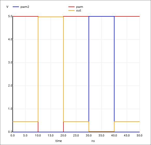
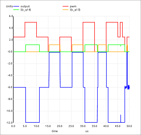
Modelling the MCU output
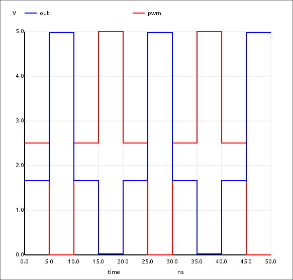
pwl

0       2.5v

1u      2.5v
1u      5v

2u      5v
2u      2.5v

3u      2.5v
3u      0v

4u      0v
4u      2.5v

5u      2.5v
5u      5v

6u      5v
6u      0v

7u      0v
7u      5v

8u      5v
8u      2.5v

9u      2.5v
9u      5v

10u     5v
10u     0v

11u     0v
11u     2.5v

12u     2.5v
12u     0v

13u     0v
13u     5v

14u     5v
14u     0v

15u     0v

---

pwl 0 2.5v 1u 2.5v 1u 5v 2u 5v 2u 2.5v 3u 2.5v 3u 0v 4u 0v 4u 2.5v 5u 2.5v 5u 5v 6u 5v 6u 0v 7u 0v 7u 5v 8u 5v 8u 2.5v 9u 2.5v 9u 5v 10u 5v 10u 0v 11u 0v 11u 2.5v 12u 2.5v 12u 0v 13u 0v 13u 5v 14u 5v 14u 0v 15u 0v
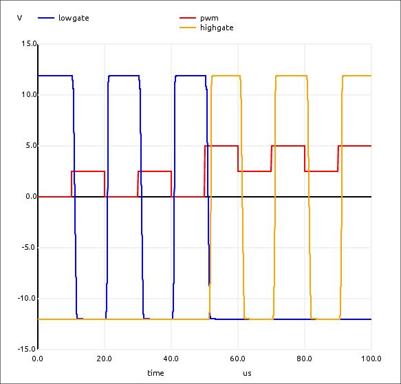
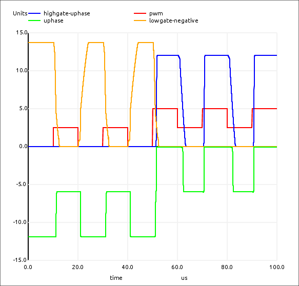
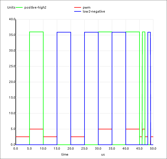
Trinary Controller Modelling
Creating a Useful IGBT Model
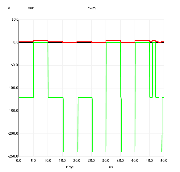
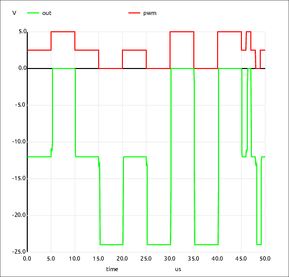
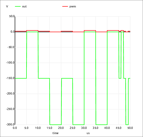
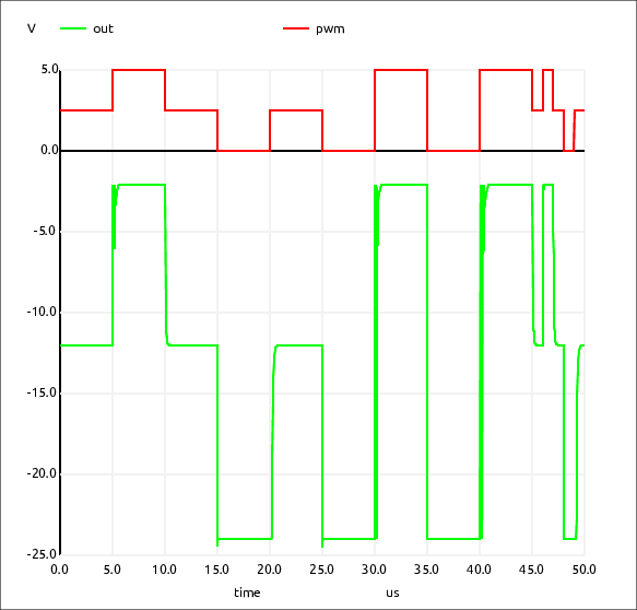
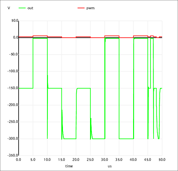
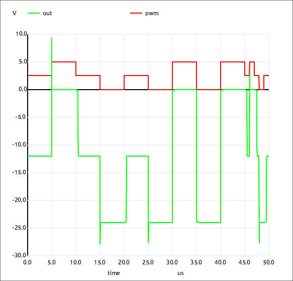
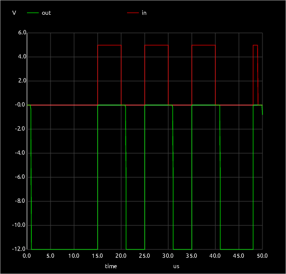
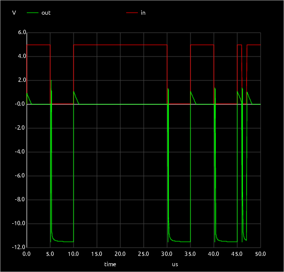
Single-Ended Output Model
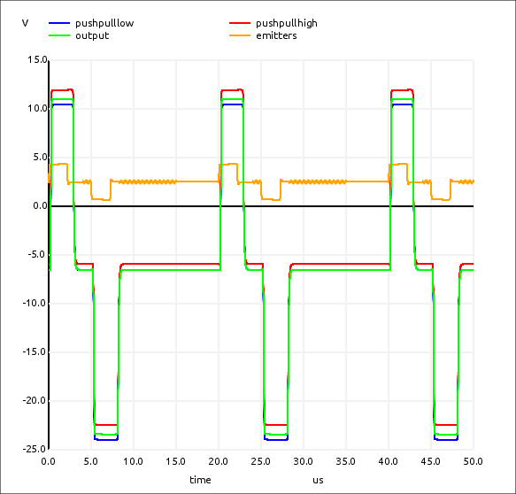
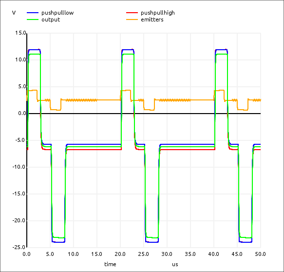
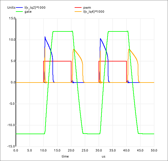
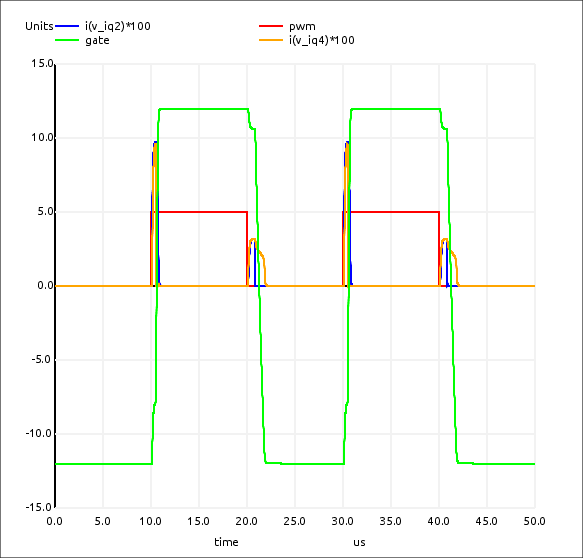
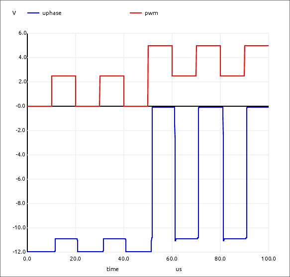
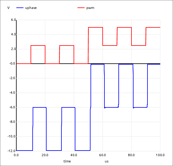 ...and with R59=100R:
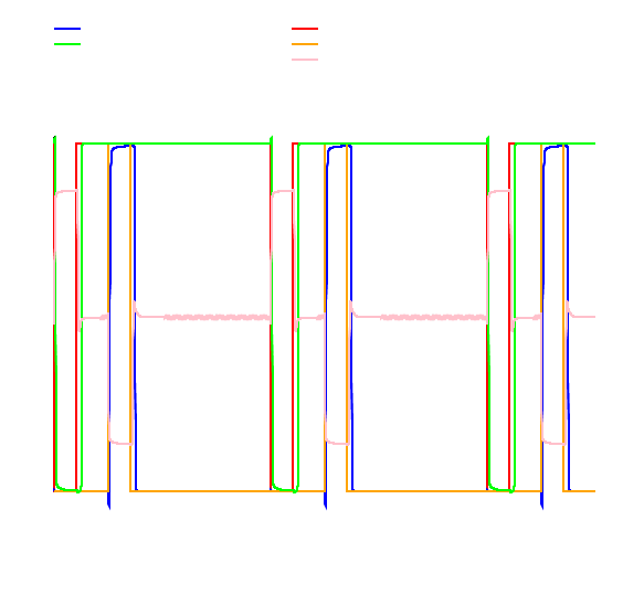
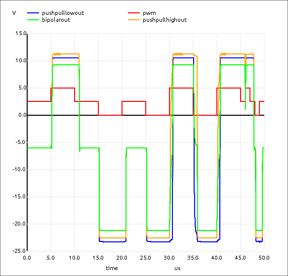
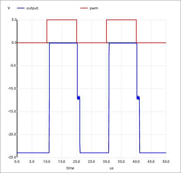
Class-D Output Model
First pass using constant current and constant voltage base drivers
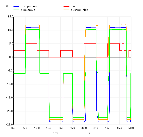
Adding fake components to class-D circuit
Fake Components
Optocouplers
IGBTs

Improving the Model with the Fake Components
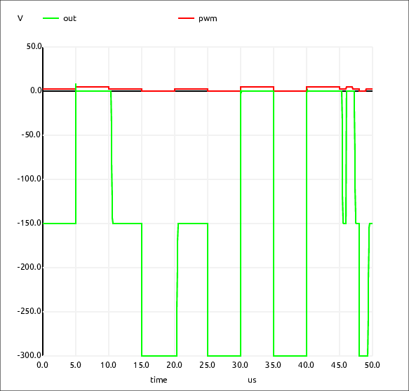
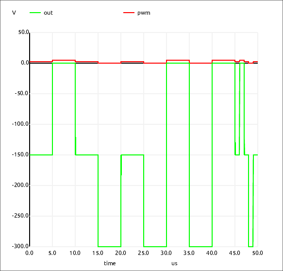
HV Direct Gate Controlled Output
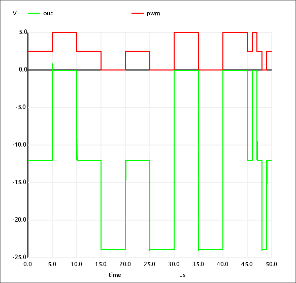
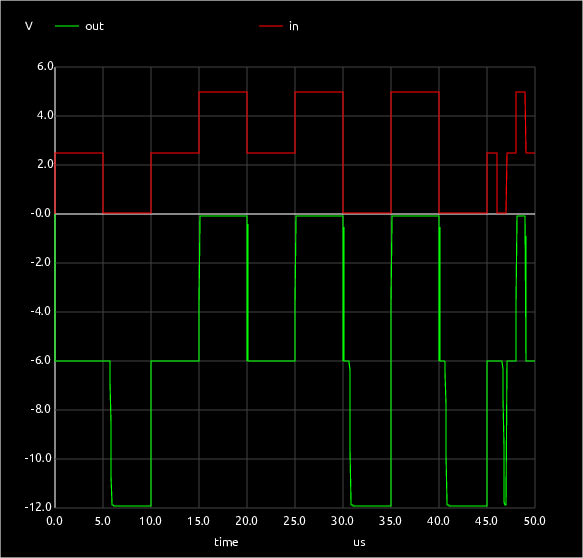
LV Gate Controlled/Class-D Output
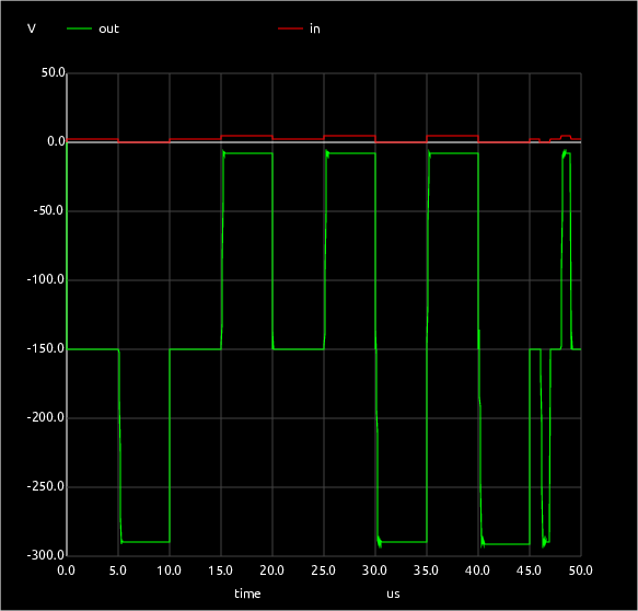
HV Gate Controlled/Class-D Output

Full Class-D Trinary
Low Voltage
High Voltage


Direct Gate Drive with Controlled Current Sources
This means the battery voltage can vary to extremes without affecting the controller operation.
Low voltage

High voltage

Low-Side Test
High-Side Test
Simpler
Single End Test