Early Controller Experiments
Since we are building a new controller using the patent method of integrated (super- or ultra-) capacitors, we need to build the controller from scratch.
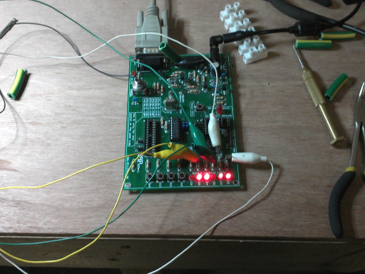
Simple relay-based controller
This is the first-principle controller using relays.
It helps to get the sequencing of the software without frying expensive components.
This very primitive model would even work when outputting PWM.
Of course, the relays will not using the AC synthesis since they will just switch, but it will help to iron out a few early sequence and amplitude bugs.
Naturally the relays will be upgraded to IGBTs (or an IGBT pack), but at £600 a pop vs less than £1 for the relays, which would you experiment with?
For the software running on the PIC see the Software Lab.
You will notice the electrolytic on the back of the CPU socket.
This is the only way to remove supply noise, and yes it has to be there!
Relay controller with transistor drivers
The next stage is to upgrade the driver relays to transistor equivalents
This is the transistor driver controller still using relays for output.
The transistors and resistor values were chosen since I had them already.
Previously, since we were using relays, we didn't need to now how much current was used in the parts of the circuit since relays aren't accurate components.
Now we are using transistors we really need to know so a few quick calculations are in order.
The PIC chip will provide up to 200mA at 5v so we need to know:
- If the current is enough to drive the BC108C transistors with our pulldowns of 15k.
- If the current from the transistors is enough for our relays.
Pin Layout of the BC108C
The relays need 46mA and the BC108C can provide 100mA so that's OK.
The current required at the base of the BC108C is 92uA for the 46mA for the relays.
The current available at the PIC is 100mA which will easily provide the 425uA needed, so no probs.
Also: because we are using the transistor as a switch, rather than a relay, we need to be careful how the circuit is organised.
A transistor is a current amplifier so the voltages are irrelevant, but to switch the transistor on we need to make sure the base voltage is above the emitter by 0.7v.
The relay will switch on when the voltage difference is 12v across the coil.
This means if the relay is connected to the 0V it's other terminal which would be connected to the emitter needs to be 12v.
This means the base would have to be at 12.7v to switch it on, i.e. well above the 5v available from the PIC.
The simple answer is to put the relay coil in the collector circuit and ground the emitter.
This way the 5v from the PIC is well above the 0.7v now require at the base to turn the transistor on.
Split rail controller
There is an issue with using the above configuration; the MOSFETS I will be using are all N-channel.
These are the most common and because of this they are cheaper.
IRL2203N N-channel MOSFET
The previous circuit uses the common-emitter configuration and puts the outputs in the collector line.
This means we would have to use P-channel MOSFETS.
What we need is the ability to driver N-channel MOSFETs which require a voltage above the source pin.
In most motor controllers the control electronics is powered from a different supply than the motor itself.
Using a split rail supply, we could power the relays from common-collector transistors.
By connecting the positive battery terminal for the output to the ground of the controller, the output has a negative rail provided by the traction battery.
This means the drivers will always be positive of the outputs.
The issue here is the base current in the drivers, which will always be above the switch on voltage of 0.7v (from the negative now, not the ground).
We get around this using an opto-coupled driver which works more like a relay and has a completely separate switch (the LED) from the transistor.
IL74 optocoupler
We just need to worry about the switch time which is 3.0uS (microsoeconds).
Given this is ultimately for a vehicle, the rotation speed is not going to be high.
A wheel of about 0.5m diameter would have a circumference of about 1.6m.
To travel at 200km / hour (which is 125mph) the wheel would rotate at 125,000 revs/hour or about 38 revs/sec.
Assuming a gear ratio of 10:1 (which is high for an electric vehicle, as some like the Tesla roaster are direct drive)
this means 380 rev/sec at the motor.
Assuming 60 poles at the stator which is 10 cycles this means we need 3,800 field rotations/sec.
For a brushless motor, each pole is switched twice for a rotation so we need 7,600 switches/sec.
The minimum period is therefore 1/7,600 sec = 132us which is well above our 3.0uS switch.
If this was the direct drive motors in the Tesla this would be going at 1,250 mph!
There is also the added benefit of having electrical isolation between the high power electrics and the sensitive control electronics.
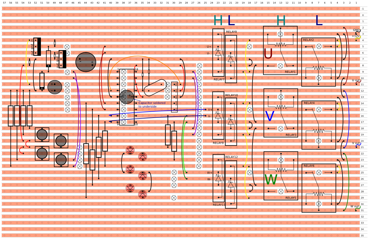
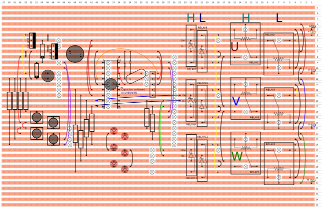
Split rail supply to drive relays using opto-coupled "common-collector" drivers
This would gives us the ability to power N-channel mosfets quite simply from the "common-collector" NPN drivers in the opto-couplers.
Solid-state controller
Now we have to replace the output stages with the solid state equivalents.
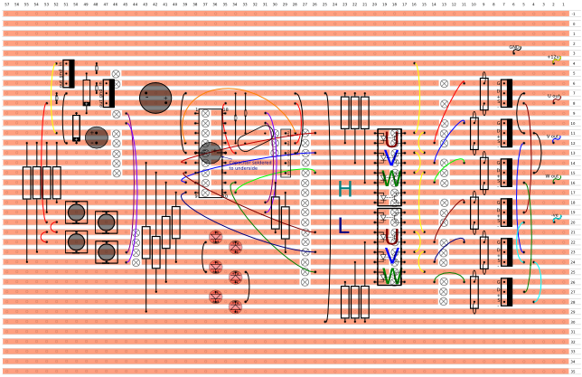
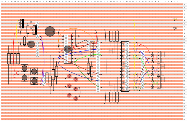
Solid-state split-rail controller using MOSFET outputs
In this case we are using MOSFET transistors.
MOSFETS are used because they are very good at using a very low power to control a high power.
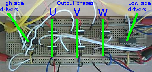
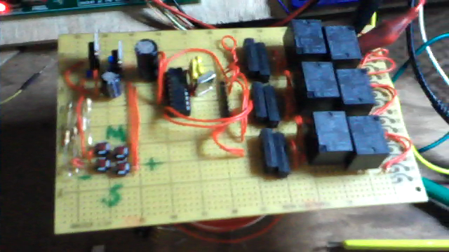
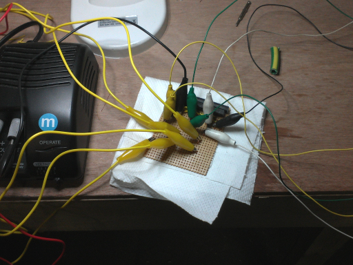
Above is the breadboard assembly of the opto isolator drivers and MOSFET outputs.
The left driver gates the high-side outputs (top 3 MOSFETS) and the right driver gates the low side (bottom 3 MOSFETS).
Obviously an extremely simple circuit which doesn't need multiple supplies.
On the left the supply shared with the PIC board is connected for the drivers.
On the right is the supply for the motor.
The low input from the PIC supply is connected to the high input from the motor supply.
The whole board cost about £20 and can drive up 33A or 400W.
Add to that the PIC16F628 used which is about £6 plus power supplies
and you can probably have the whole controller in less than £50.
Simple and cheap.
MOSFETs work a bit differently to normal transistors in that they just need an electric field or charge on the gate to switch on.
It's like you need to think of the gate circuit like a capacitor and not a resistor.
This field is quite small, but needs to be above a certain voltage to switch it on.
So the speed of switching, not the amount of drain-source current, is determined by the gate current.
And the voltage on the gate determines the drain-source current.
If we say we want the MOSFET to turn on/off in 1 us (microsecond) this gives us the values of the switch off resistors.
PIC Analogue Timers
...using a 555 monostable triggered by the PIC and fired back into it.
Varying VR1 varies the time period killing two bird with one stone.
The software can use this instead of an internal timer making it separate to the software and this provides analogue control without ADC input.
See PIC Analogue Control for the software.
This would use two pins for each monostable circuit.
Two monostables: one for each mark and space; so 4 pins on total.
This removes the need for the buttons so this is a straight swap for them.
IPM Controller
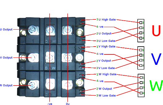
Here, since Turbo Electric has discovered the specification for the PM200CVB060 (also the PM600CVB060) IGBT power module used in the Toyota Prius,
we can use the controller to power the car directly.
This will obviously be currently in brushless DC mode and not AC synchronous mode as is used in the Prius.
That will come later.
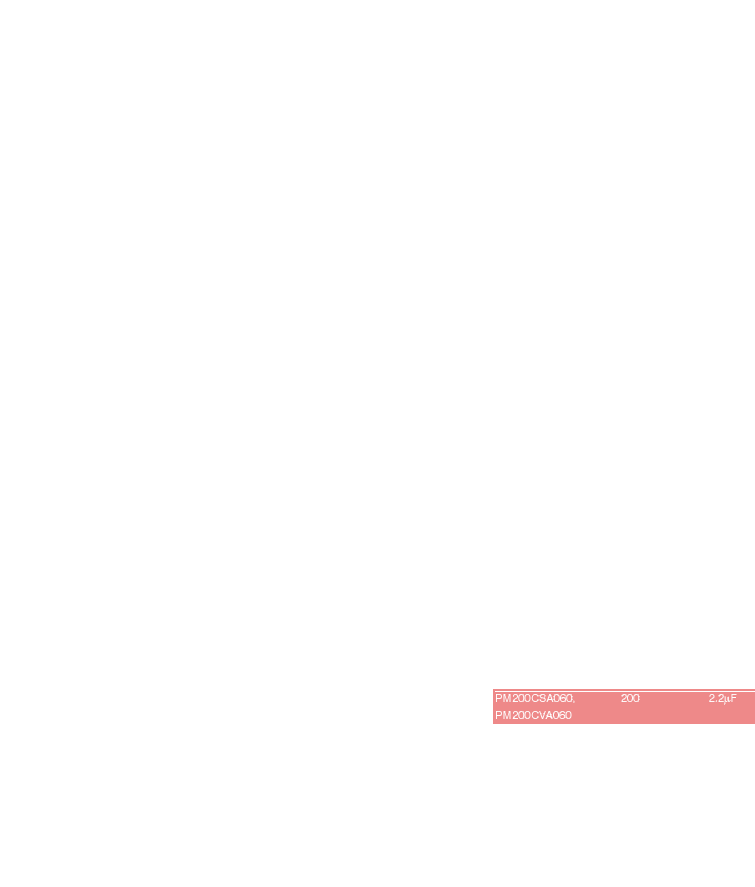
PM200CVA060 and PM200CVB060 Block Diagram.
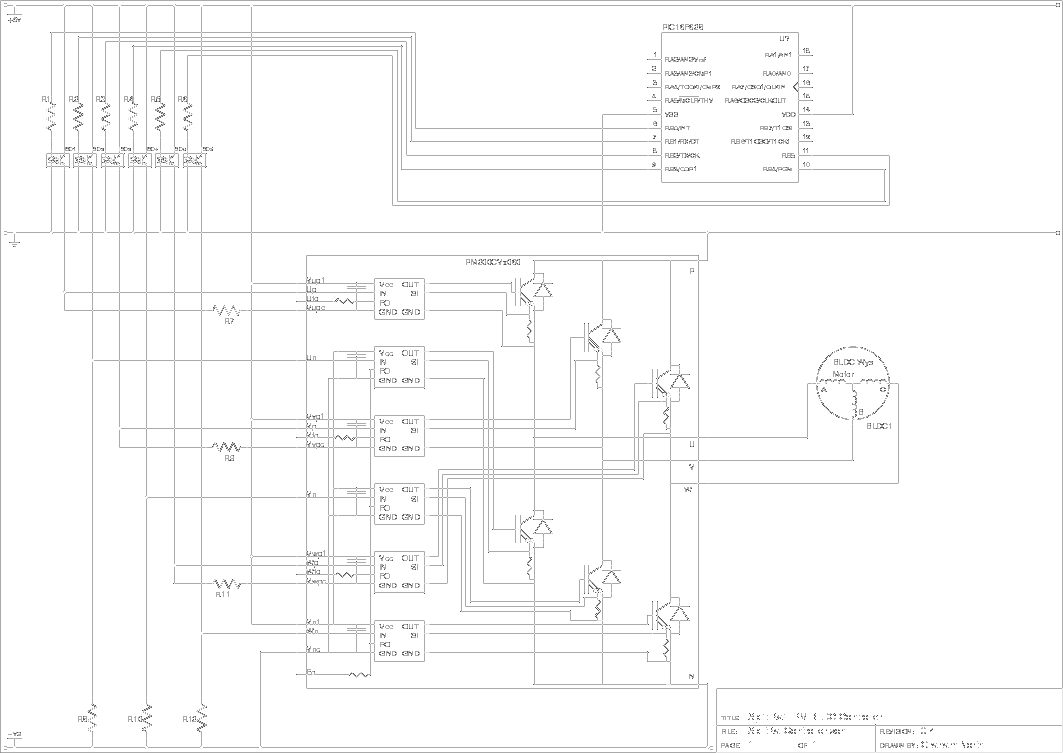
Split-rail controller diagram using the PM200CVx060 IPM.
Unfortunately I haven't got this to work yet.
Mitsubishi, the manufacturer of the IPMs, have produced a document on how to use their IPMs.
The PM200CVA060 is listed as one of the parts to which the document applies,
which means it should equally well apply to the PM200CVB060.
Here is a copy of the document.
This includes a diagram using opto-isoloators:
The inputs are inverted and the fault outputs need to be tied high to prevent false faults.
Here is the new diagram.
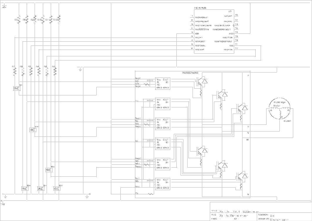
This means R7-R12 should be 20k (referring back to the Mitsubishi diagram)
There is an issue here in that the input voltage for the IPM controller side is quite limited.
If it is intended to use this on a high voltage system this will not work.
It may be possible to physically open the case and connect to the IBGTs directly, by passing the input circuits.
This means I will be able to implement the solid state FET circuit above, which has been tested and works.
Mitsubishi have obviously made assumptions about the kind of input circuits that this device is going to use,
however the single split rail input obviously reduces the complexity of using 4 or 6 separate isolated supplies (and the cost) by several orders of magnitude.
It is our belief that (like Einstein) things should not be complicated if it is possible to make them simple.
The "Solid-state split-rail controller using MOSFET outputs" circuit is indeed simple and it has been tested and works.
The only issue may be the gate-source voltage which could be beyond limits.
This can be restricted by inserting a resistor-zener diode circuit into the gate input circuit.
IGBT Controller
After much coaxing to get the IPM to work, I decided I was attempting too much at once.
So I purchased 3 IGBT dual modules and used them instead.
I may try the IPMs again after testing this as I have quite a few now and it would be a shame to waste them.
The IGBT packs are Fuji 1200v 450A units and cost just over £200 each from RS.
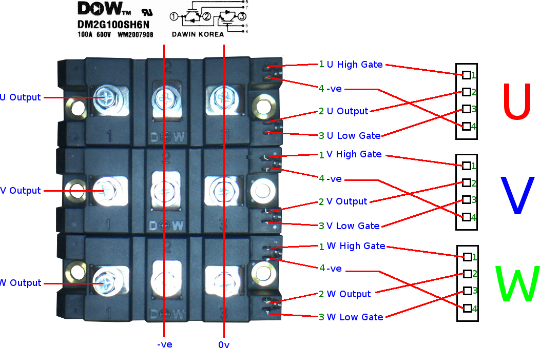
2MBI450U4N-120-50 IGBT pack
So I simply modified the MOSFET circuit to use the IGBTs instead and this worked fine.
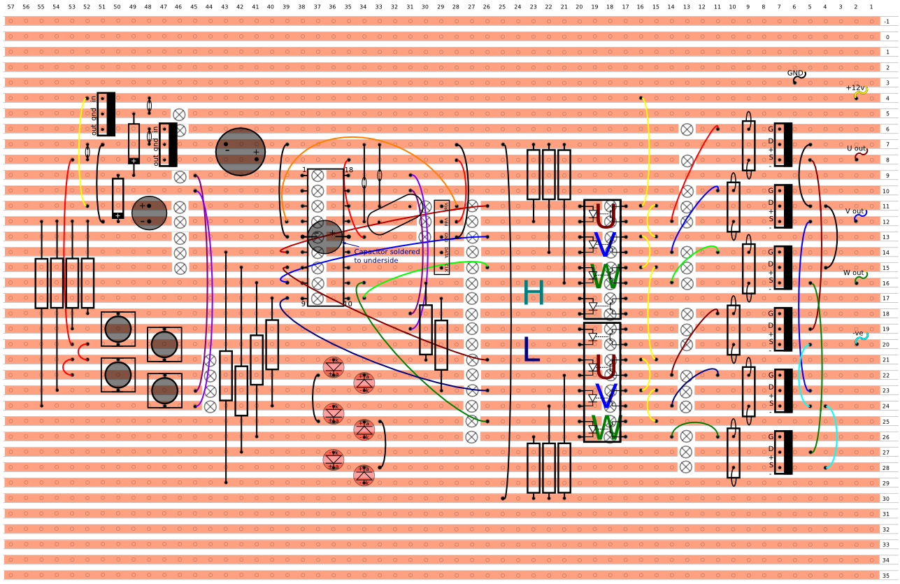
This is the new circuit:
You will be able to see the MOSFETs are removed and the IGBT packs are dropped in pretty much pin for pin.
It was running my little helicopter motor at 3v no problem.
This means in theory I should be able to substitute the 300v battery for my 3v power pack
and connect up the Prius motor, and we should have a car in motion.
Although I will probably need some 15v zener diodes across the gate-emitters since the packs are rated at 20v max gate voltage.
In car testing
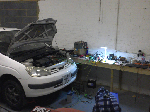
Since Turbo Electric is based in a new workshop on Milford Road, the controller testing is going to continue on an actual car.
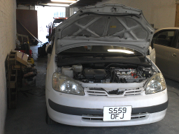
The white Prius above has been transported to the new workshop so work will begin soon to test the controller circuit on it's traction motor.
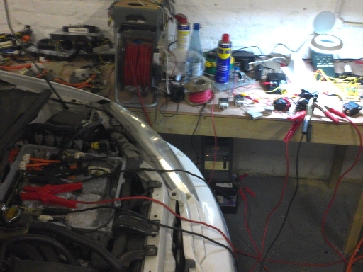
Given the power requirement of the motor in the Prius, it is best to go back to first principles to start testing.
So we are pulling out the relay PCBs again and upgrading the output relays with some high current relays to test the circuit.
Betting this than fry expensive IGBTs, of course.
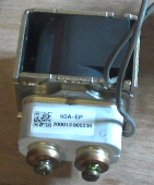
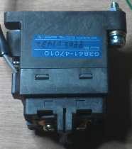
There are some high current isolator relays in the battery circuits, so they were salvaged and put into use.
Not sure what these babies can handle on the switch contacts, but it's alot!
They are used to isolate the battery at full power (~300V at hundreds of amps) so they are good enough for this.
They will probably get fried when using then to repeatedly switch the motor currents, but they are not needed for anything else.
The coil needs 12v and a measured 30ohms means they require 0.4A.
Our reed relay contacts are rated at 500mA so they will drive the power relays no probs.
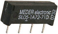
Reed Relay RS:291-9669
I was trying to find a spec sheet for the power relays to get the exact contact rating, but it didn't seem to be available.
The current was measured at 12vDC into the Prius motor inductor and it was about 60A which means a resistance (at DC) of 0.2 ohms.
At 300vDC this would be I = V/R = 300V / 0.2 ohms = 1500A
Power rating P = VI = 300V * 1500A = 450000W = 450kW
I know the motors are no where near 450kW (nearer 30kW) so we need to control this output down.
Voltage for 30kW is V = SQR(PR) = SQR(30000W x 0.2 ohms) = SQR(6000) = 77.46V
Current at 30kW is I = SQR(P/R) = SQR(30000W / 0.2 ohms) = SQR(150000) = 387.3A
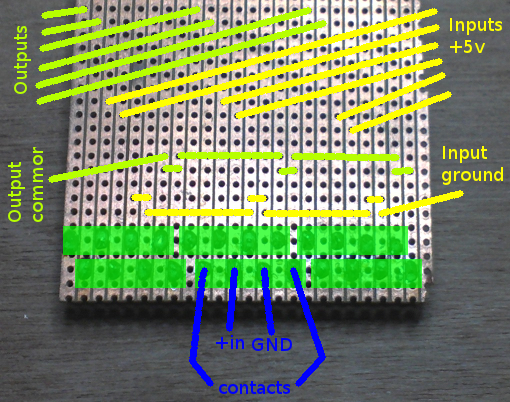
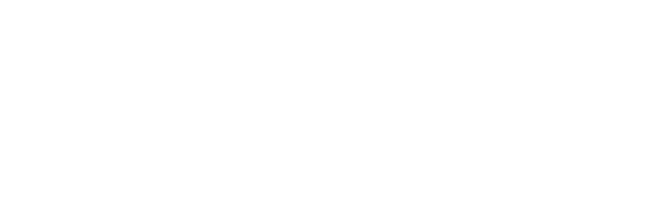
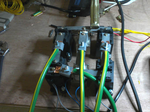
Bit of VeroBoard for mounting the reed relays.
Final board with croc-clip terminals.
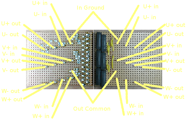
Relays connected in a 3-phase bridge with some purpose made bus bars.
The bus bars were machined from a bit of chassis mount.
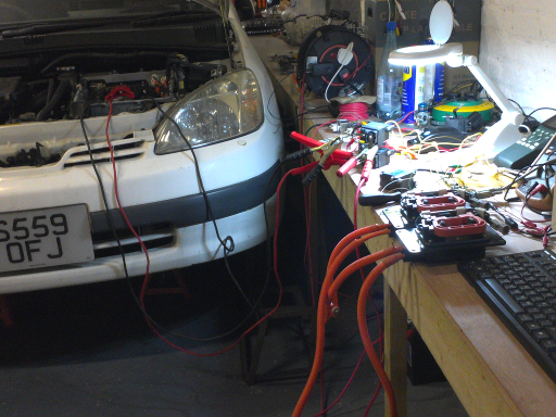
Prius powered by a PIC
This is the full circuit now powering the Prius motor and wheels
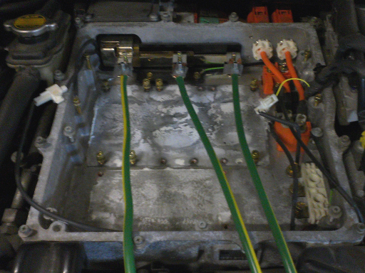
This is obviously low tech, but it tests the wiring and load currents prior to using the IGBTs.
And we are not using the sensors to detect shaft position so it's still quite dumb.
Adding PWM
To start we need a circuit to simply control a series wound brushed motor.
So this is just a simple PWM circuit
This is using one of the IGBT dual packs since we have them.
In this circuit we are just using the low side transistor.
Obviously, the above IGBT circuits for BLDC will work fine for BLDC commutation or using AC synthesis
so they do not need adapting specially to add PWM.
This circuit is initially to control a mechanically commutated motor, but it could also become the supply for a brushless motor too.
This would have the advantage of modularity, but it would cost more as you would need another IGBT.
This was the circuit actually tested.

Just a quickie to see it working and get an idea of the current used.
It seemed to peak at about 27A on 12V.
P = VI = 12V x 27A = 324W
R = V / I = 12V / 27A = 0.44 ohms.
This doesn't take into account the cable resistance which would be affect the result.
at 48V:
P = (VxV)/R = (48 x 48) / 0.44 = 5,325 W or about 5kW.
I = V/R = 48 / 0.44 = 109A
The new combined PWM and BLDC algorithm was also tested:
This is the modified BLDC code to include PWM.
Direct drivers
It occurs now the original reason for using optoisolators, as solid state relays, is no longer needed.
So why not drive the IGBTs directly as a normal amplifier?
This mean much faster switch speeds can be achieved.
This circuit does away completely with the decoupling.
Switching speeds of under 100nS are easily achievable without expensive components and power supplies.
This is only possible because the controller is designed with the unique patent split rail supply.
IGBT direct drive PWM testing
The good news is that: replacing the MJ2955 with the faster and higher voltage KSP94 means
the switching is once again a nice square wave at the IGBT gate.
PWM Controller Initial Testing:
Milk Float Motor Temperature Testing:
Milk Float Motor Peak Current:
Milk Float Motor on 2 x 12v Batteries:
Schematics and layouts were done in gEDA gschem and PCB,
drawings in Inkscape,
models in Qucs (Quite Universal Circuit Simulator),
imagery in gimp,
video edited in avidemux