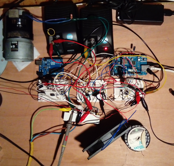
Separate to the development of the 3-phase controller, handling the power requirement was also required.
The intention is to use simple electronics and deal with the issues of high power electrics separately.
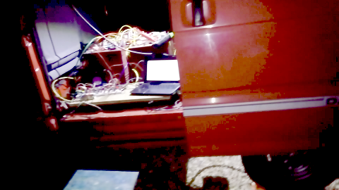
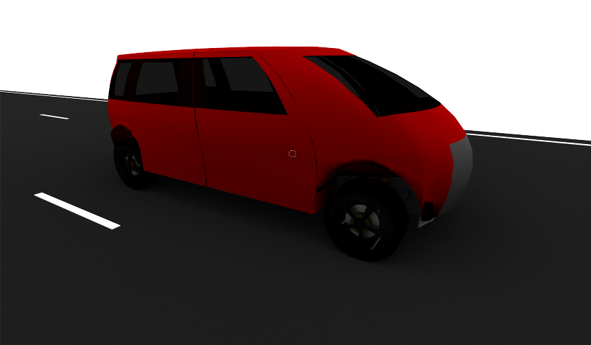
To that end a test-bed vehicle was made by converting a Daihatsu HiJet van.
This was selected due to the access under the floor to the power train.
The van floor was completely removed as was the existing piston-engine power train up to the prop shaft.
Then an ex-milk float motor was added and connected directly to the prop shaft.
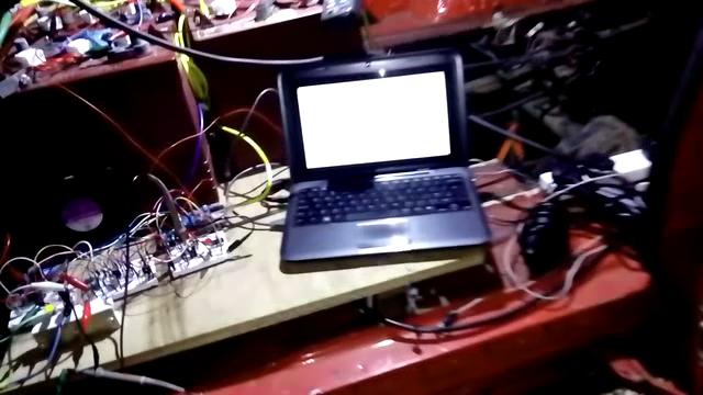
Also a wooden bench was fitted in the van over the motor for experimentation purposes.
The basics
This circuit is just for reversing the series wound milk-float motor using contactors:
Since a full operational G-Wiz, and also some parts including batteries, brushed DC motor,
and the original Curtis Sepex controller was obtained testing has moved onto using the G-Wiz brushed motor.
So we now have a stable circuit at 48v (low power).
Just to verify the actual output voltage.
Also we have gate switching at the target 1uS (both rise and fall).
Using Base Tuning
Using 220R and 1k trimmer in parallel gives a range of about 0-200R on a trimmer.
This means the bipolar base can be tuned to give the best collector output.
Also added C2 to ballast the gate charge/discharge spikes and C1 to help smooth the MCU supply.
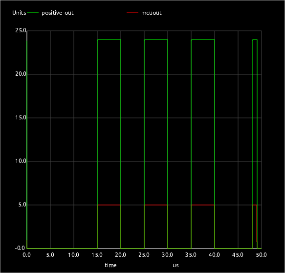
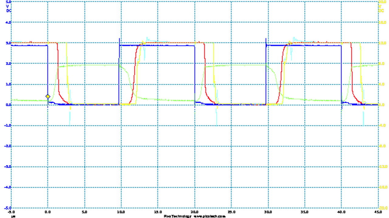
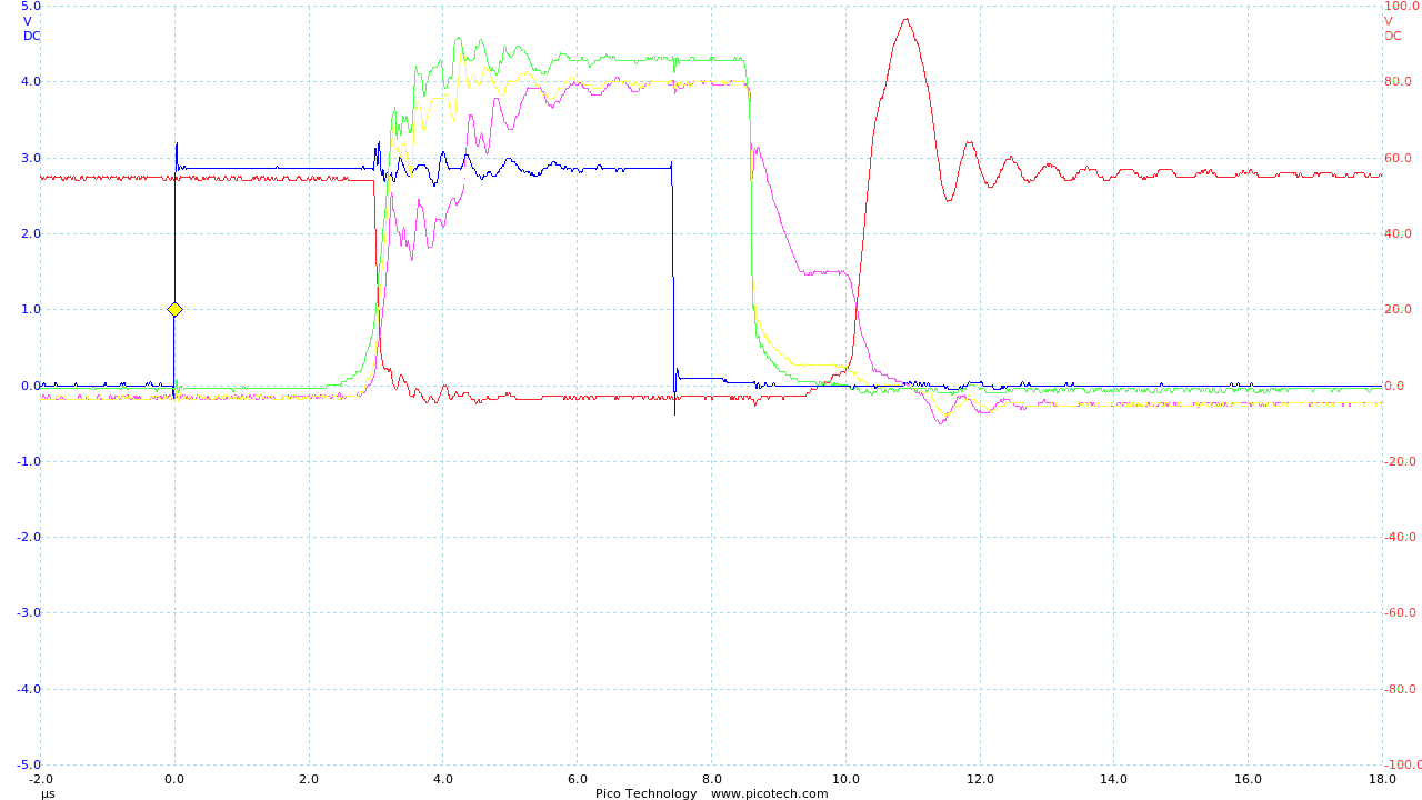
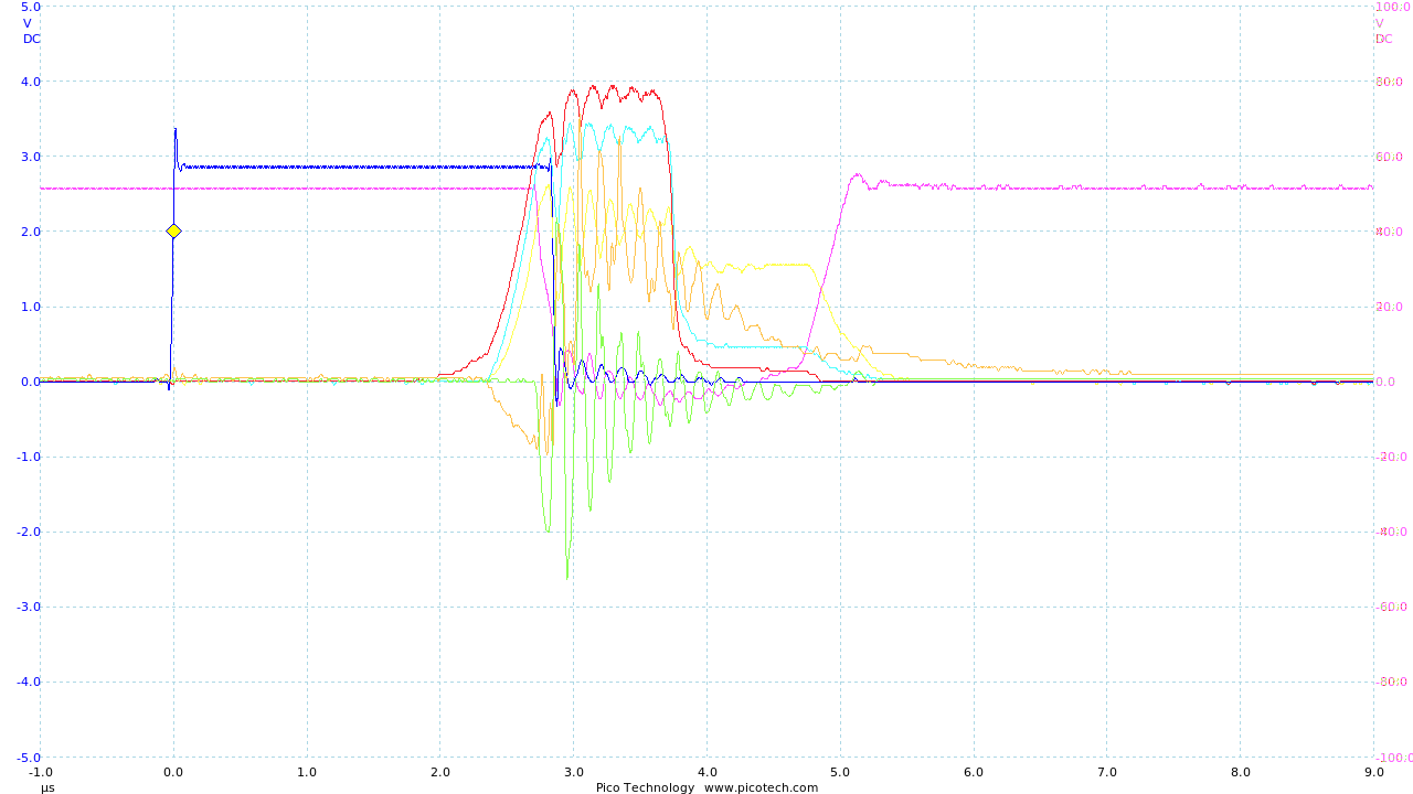
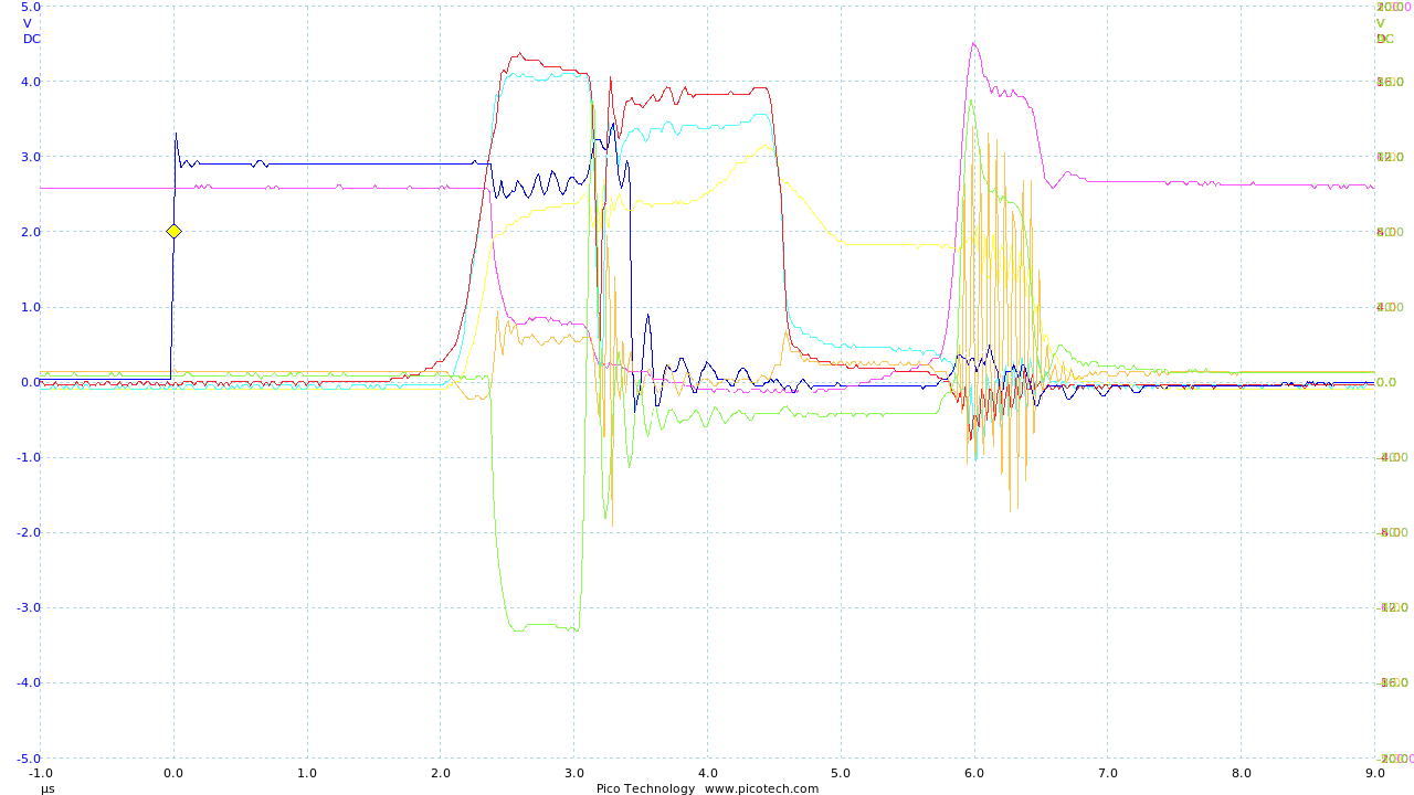
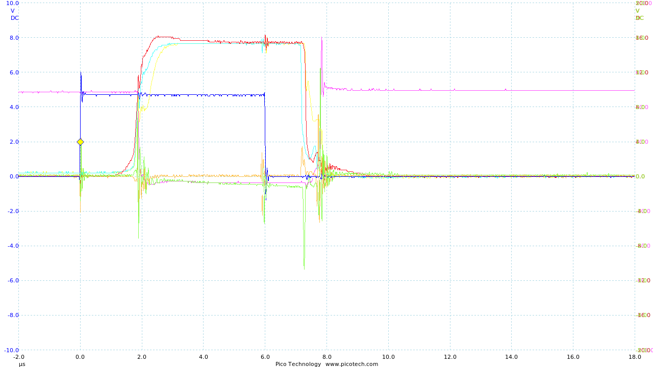
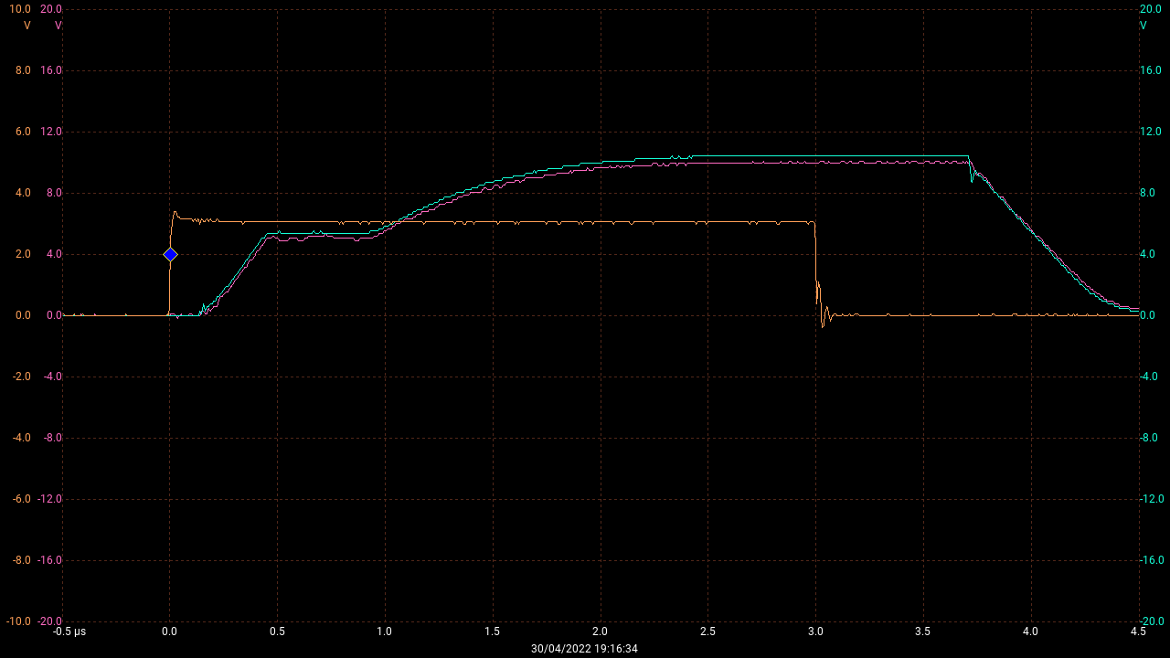
So now a good square can be tuned for the driver stage:
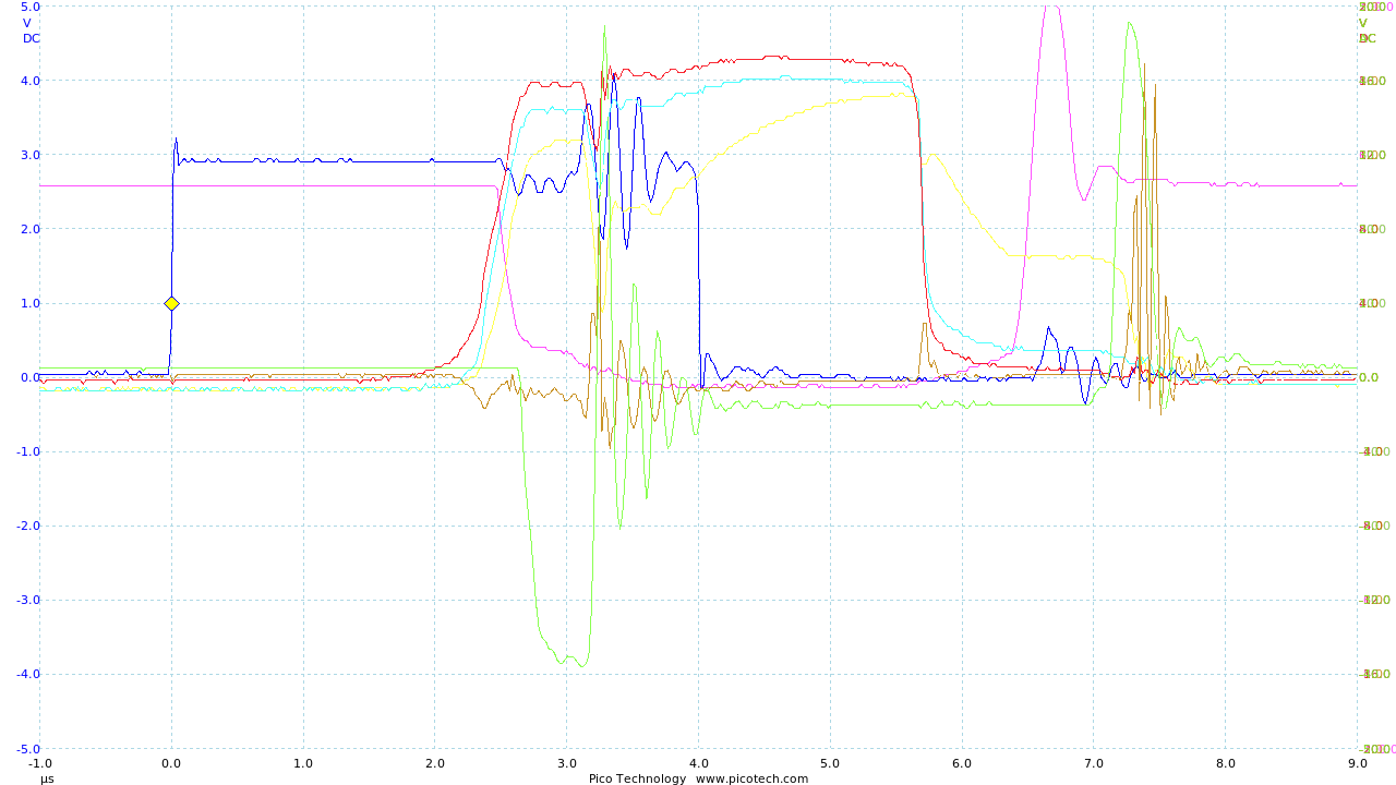
Blue is MCU1 IO36 (1v/div), Green is Q1c (500mv/div), Red is Q5e/Q6c without gate connected (4v/div), Yellow gate connected, Cyan with M1/D1 attached,
5uS/div 50kHz 50:50 mark/space.
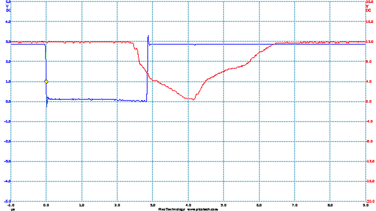
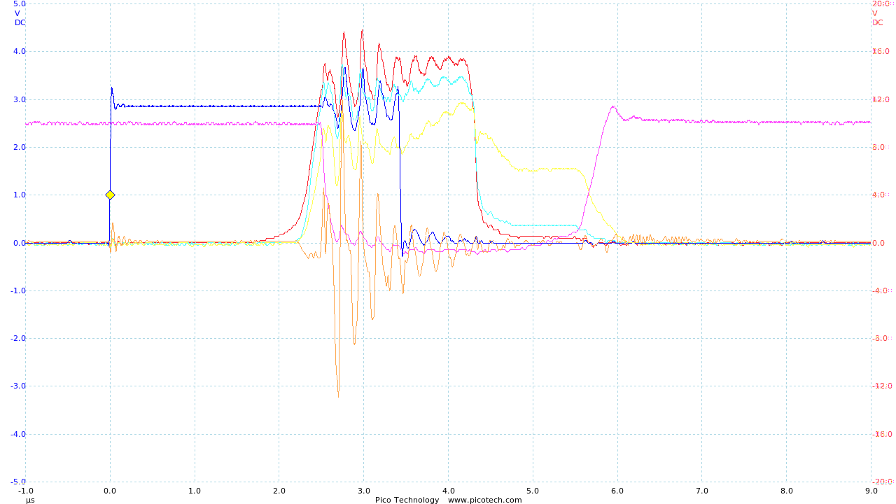
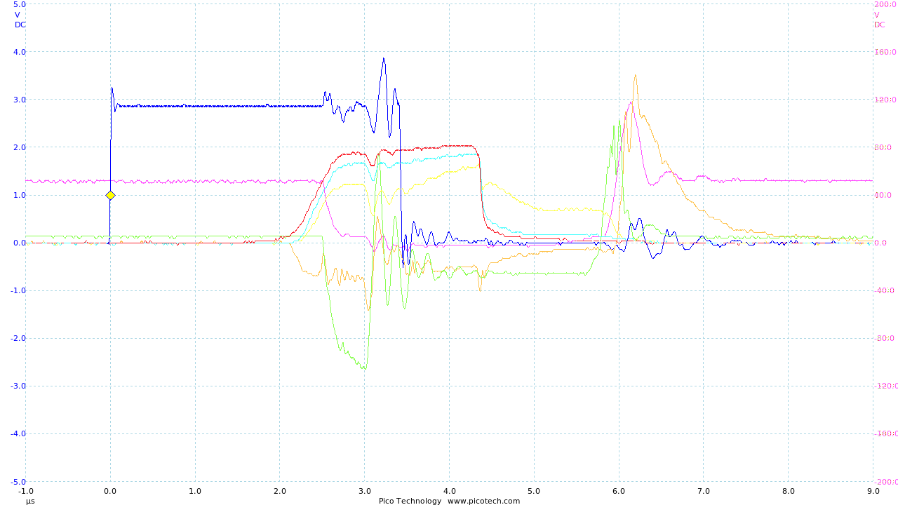
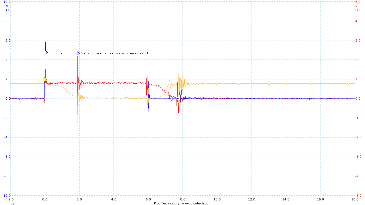
Blue is MCU PIN36 output, Red is gate without M1/D1 attached, 1uS/div 100kHz near 100% mark.
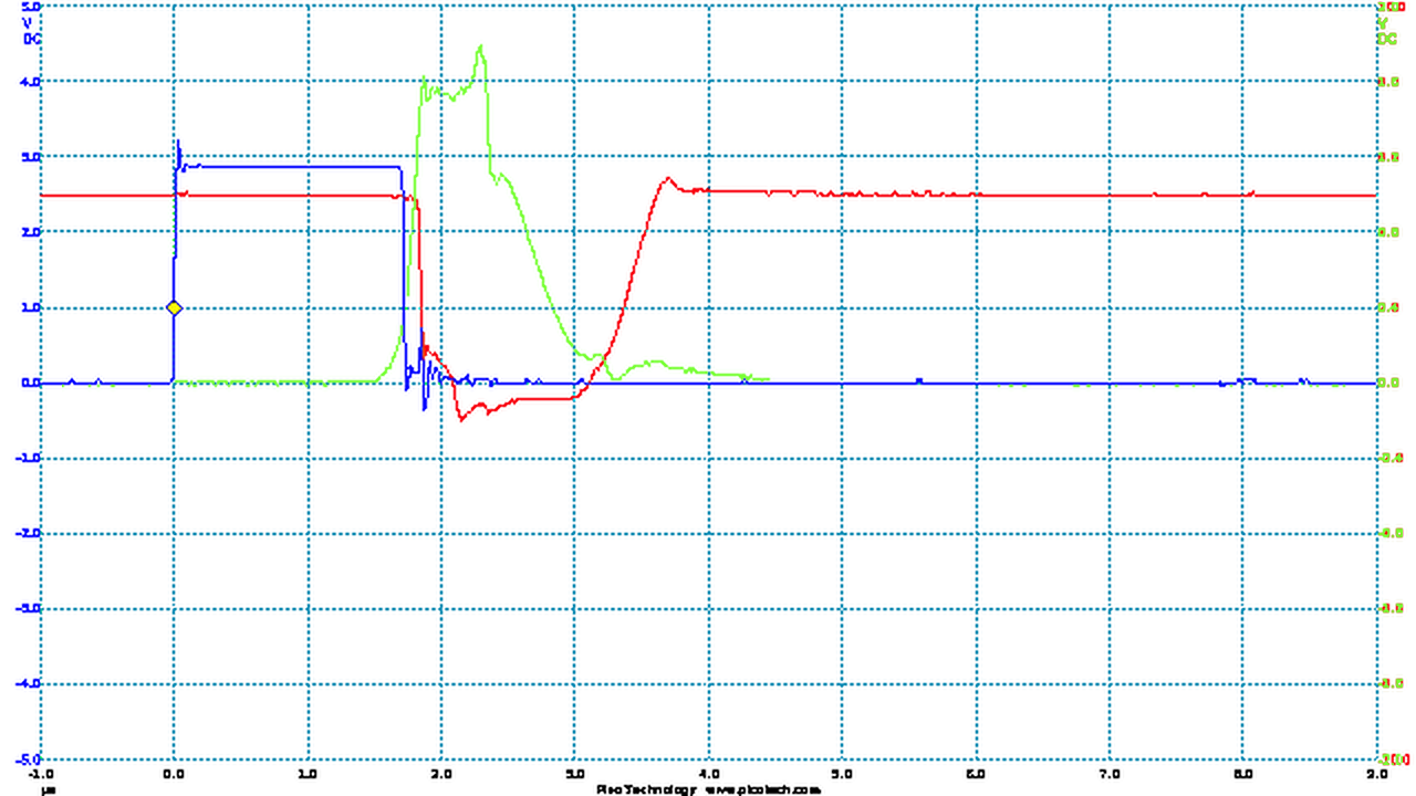
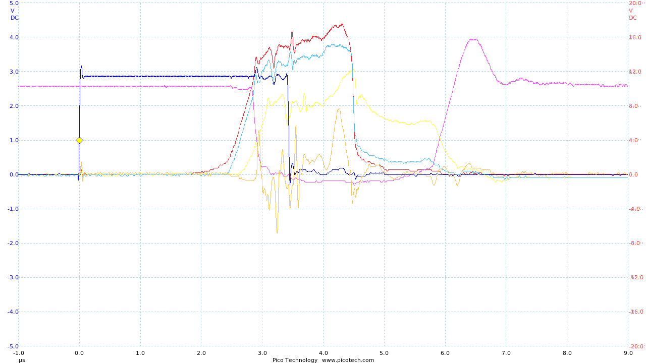
Blue is MCU PIN36 output, Green is gate, Red is IGBT1c, 1uS/div 20kHz near 0% mark.
An alternative to using a zener to cap the gate voltage is to provide a LV supply for the driver circuit.
The problem is that about 2v is lost on the gate is the battery discharges to a low voltage, so the gate may not switch well,
but it means that the gate should switch on cleaner against the LV supply using C2 as ballast for the spikes.
Also 11R series gate resistance was added to attempt to dampen the charge/discharge ringing.
There was a failure in the regulator circuit which made the gate switch to +48v.
This could blow the gate of the IGBT so added monitoring of the driver supply.
Since adding a voltage monitor there should be one for the battery too.
Added a contactor controlled by the MCU, also voltage level inputs.
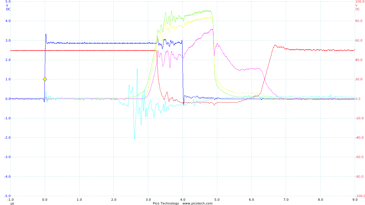
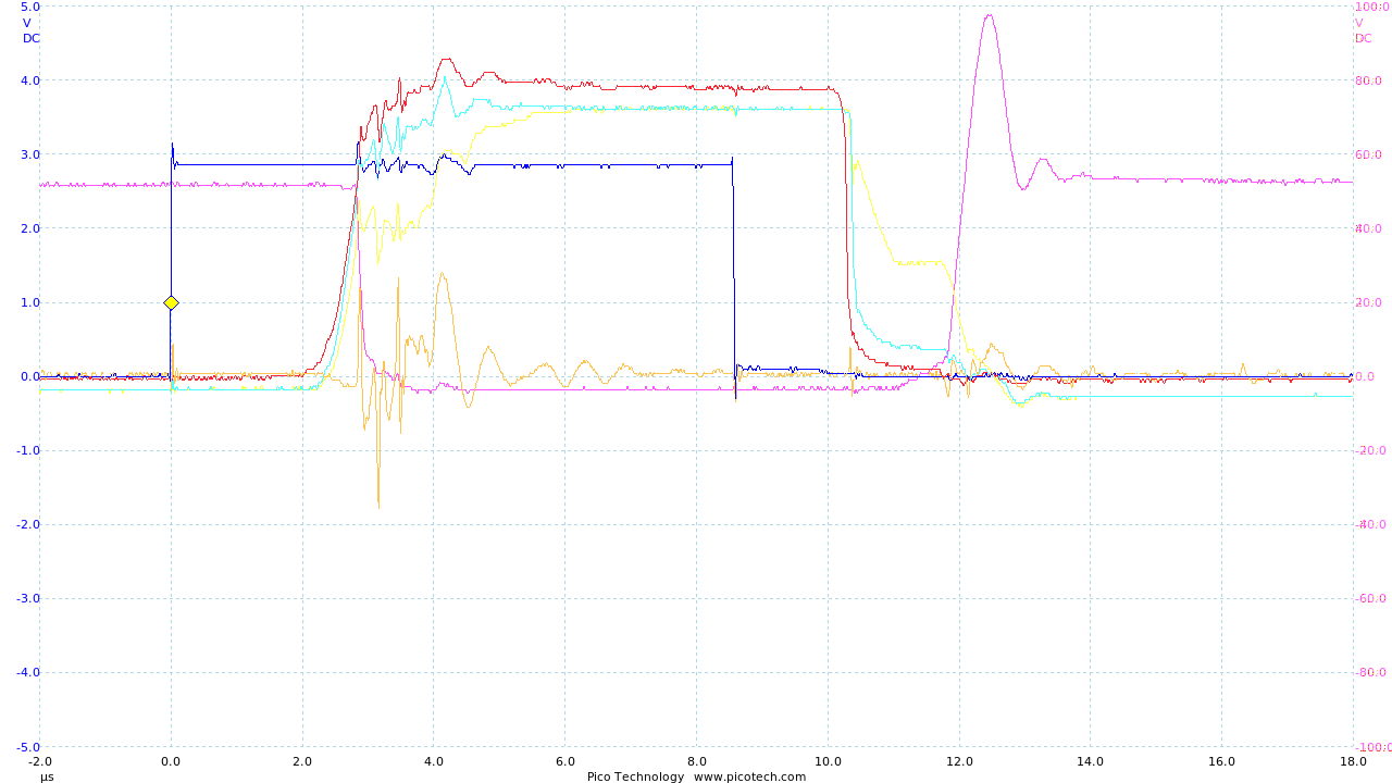
The circuit seems fast switching (transitions are much less than 1uS) but the problem is noise.
The frequency of that supply oscillation is ~6.4MHz, period ~156nS.
The on delay from the IGBT spec is 150nS so could be that.
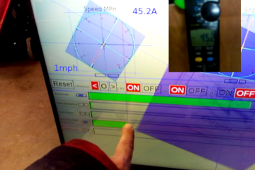
Circumference = π * diameter = π * 0.53 m = 1.67 m
For approx 50% mark:
Time for 1 rev: 1:30.321 - 1:29.954 = 0.367s
speed = 1.67 m / 0.367 s
speed = 4.54 m/s
speed = 10.15 mph
For approx 75% mark:
Time for 10 revs 49.460 - 47.227 = 2.233 s
so 1 rev is 0.2233 s
speed = 1.665 m / 0.2233 s
speed = 7.457 m/s
speed = 22.70 mph
So the next step is to allow the motor to move the van.
This will need a wiring upgrade first.
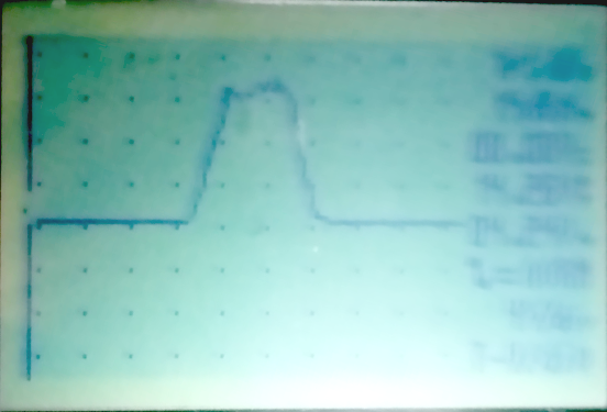
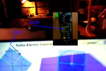
Then a short test to see the van move an inch or two (at night hence the quality):
The van is very heavy (around a ton) so this is just a test to see the controller respond to actually moving the van.
During the test the IGBT temp remained well below 50°C with no heatsink.
Capturing the peak current in the move.
This is from a ~50v battery so the IGBT was passing ~40A x ~50v = ~2000w
The motor is believed to pass ~200A at full power on 44v so about 9kW.
On this battery it will maybe be nearer 10kW so this brief test was on 20% full power.
Creating a usable controller
Moving to using an UNO since ATMega328 chips were obtained so this can be mounted on a single PCB.
The current needs to be monitored also since no component is unlimited.
This should be relatively straight forward using a ratiometic hall sensor.
From the datasheet the SS495A has a range of -670 Gauss to +670 Gauss [-67 mT to +67 mT].
On the Arduino this means ADC 0 is -670 Gauss and ADC 1023 is +670 Gauss
From Magnetic Field of Current the relationship of field vs current is well understood.
For a wire of thickness 12mm (diameter) and adding 2mm for the device.
Field: B (tesla) = μ0I / 2πr
Permeability of free space: μ0 = 4π*10-7
Field: B = 2 * 10-7 * I / r
Distance from the hall sensor to the centre of the wire (r) is 8mm.
So: B = I * 2 * 10-7 / 8 * 10-3
B (tesla) = I * 10-4 / 4 or just B (gauss) = I / 4 Gauss
I = B (gauss) * 4
ADC input to field is B = (adc - 512) / 512 * 670 and to current I = (adc - 512) / 512 * 670 * 4
I = (adc - 512) * 5.234
While this is not very accurate: we can only measure around the nearest 5 amps,
it's good enough to ensure a limit in the hundreds of amps is not exceeded.
Testing for real on ~20A seems to roughly back up the maths (ADC dropped ~6), so the software can be adapted.
Not expecting accuracy here, but just to ensure there is something usable.
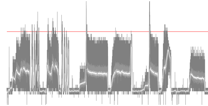
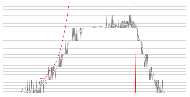
This is the current seen by the controller during the test:
Shades go: current sample (darkest), moving average over 4 samples, then 16, then 64 (white)
The IGBT is allowed to exceed it's constant current rating of 100A for brief spikes, but is reigned in quickly.
The average load seems to be held at around 35A so the device could probably be allowed a higher limit, but in this test the controller limits well.
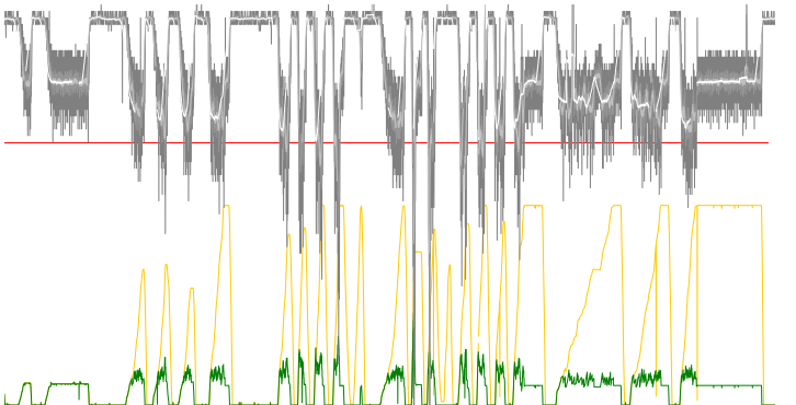
Now testing on the vehicle with the wheels on the ground again.
Basically the current limit is not high enough for it to move much, but that's the point.
Yellow is control input, green: motor output
and the top plot is current (raw-grey, 4 point moving average, 16, 64-white)
Obviously this is limiting the power output as you can see the green plot is being capped.
The motor was held stationary so the max power output was expected to be the same.
Possibly the current sensor is too simple as the sensing is sampled at a low frequency (in the 10Hz to 100Hz range) and may miss the peaks.
Maybe develop a circuit with an amplifier and capacitors to store the peaks for a 100mS so the sampling is more reliable.
More Sensors For Less
For testing purposes all the thermal sensors will need to be observed individually.
In the final controller they can probably just be bridged as only overload is needed and should be a rare occurrence.
Thermal sensors don't spike or change very quickly.
So the addition of an external multiplexer allows this.
This actually allows for 8 inputs but only 5 are use in this circuit.
Also the junction voltage drop across the diode needs to be included in the software to be accurate.
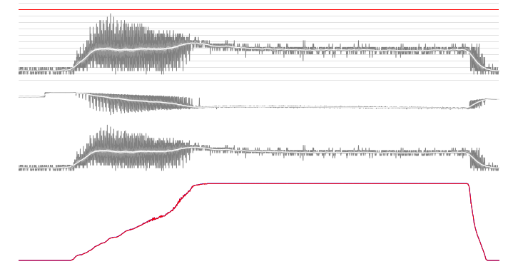
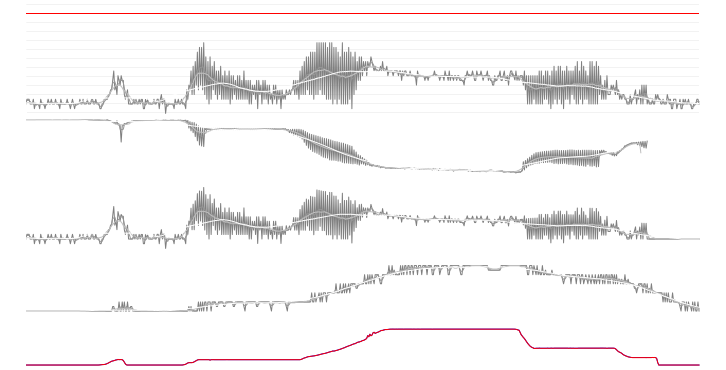
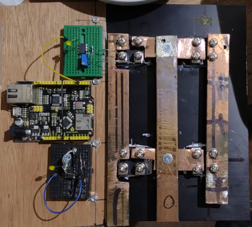
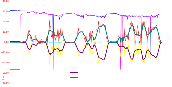
So now this is the final build of the electronics.
Peak observed during the test was 50.8A and this is also observed by the controller.
Top to bottom: current (A), voltage (V), power (W), and control input (left scale), motor PWM output (right scale)
Since the power is showing the same scatter, it seems the sensors are tracking the real PWM peaks and the noise is just a constant.
49v NMiH Battery to 44v 200A Series Motor
Also at this point the circuit noise is minimal so we can loose the gate resistor and have faster more efficient switching.
Shaft Rotation Detect
Something missing from the controller, which would be needed to display roadspeed
and ensure restriction for DVLA (UK driving authority) reasons is the ability to detect rotation of the shaft.
It would also be useful for the controller to detect if the shaft is turning as expected.
This can be added using a simple hall switch and a magnet on the shaft.
The controller just times the pulses from the hall switch to get the speed as the gear ratio is fixed at 40:9 in the diff and each wheel rotation is 1.67m.
Just a quick test to assess the usefulness:
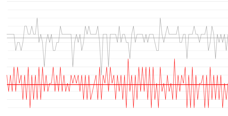
Left scale: rotations per 100mS, right: MPH, the red line is the control.
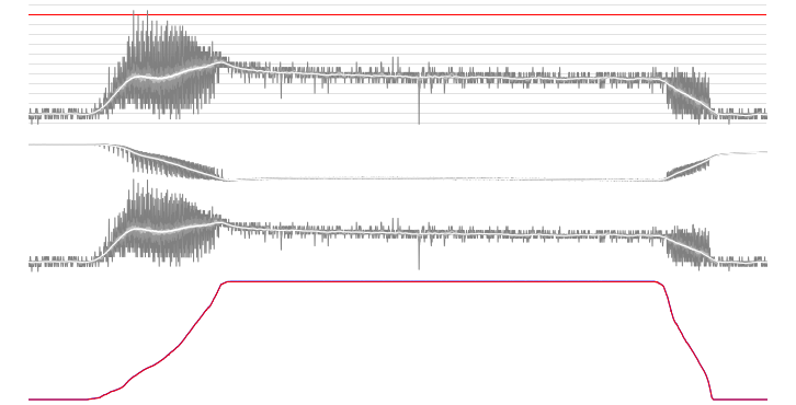
Incorporating another run into the graphing:
Top to bottom: current (A), voltage (V), power (W), Speed (MPH), and control input (left scale), motor PWM output (right scale)
So the gearing of the vehicle will allow up to 45mph so 30mph should be attainable.
Road Testing
Just a short road test to show it moving under it's own power:
The first test (above) was using a hand held control, but a foot operated control is needed.
A simple cable operated one does the job for now:
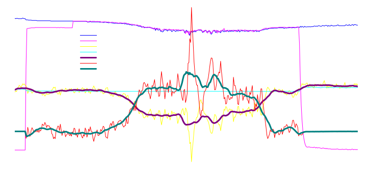
Took it down the street, 3-point turn and came back.
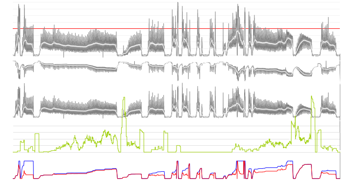
Top to bottom: current (A); voltage (V); power (W); left:Speed (MPH), right(yellow):economy (MPGe); and left(blue):control, right(red):motor
The motionless sections of the graph are truncated.
The speed is not very accurate currently, but a software revision will fix that.
During the run the controller handled a peak current of 414A and many times held the motor at 200A (over 10kW) without problems.
The outbound run was 12 seconds and accelerated to 15mph, the return was 8 seconds and got up to 13mph.
Also since both the power and speed are measured in the controller it's possible to calculate the efficiency.
Even convert it to MPG equivalent, which in an electric vehicle moving at around 15mph is around 500MPGe
Also on
The van accelerated to 17mph before stopping with the brakes.
Upgrade
Modern components make the circuit now very simple:
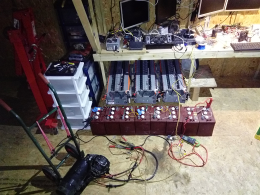
This is so the batteries can be tested at high current.
As you can see above the current draw was 200A constant and over 400A peak.
This is at 48v for a 10kW motor.
If this is in the Mass-EV which runs at 400v it will be 160kW per pack and there are 3 parallel packs so 480kW total, or about 650hp.
This van will be put back on the road and used, so some real-world testing will give the usability of the batteries at these high powers.
In the above graph the speed was held at 10mph by the brake which gives us a peak torque of 136.56Nm (16.44kW or 22hp @ 1150rpm).
If this was the torque applied at 60mph this would be 220hp, which is the about target power of 200hp.